- General Details
- Order Enquiry
- Documents
General Details
Water Level Control Module
Type “WLC”
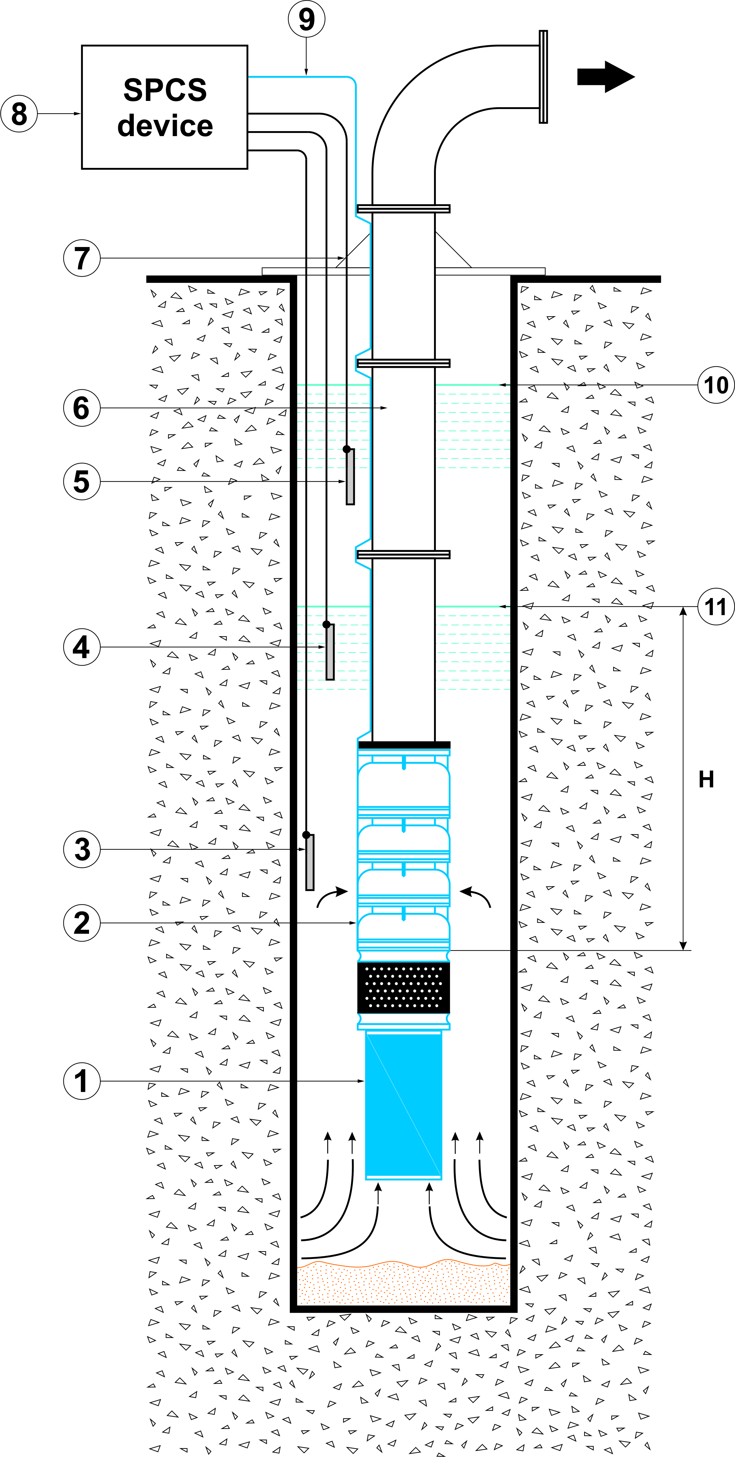
The “WLC” module is designed for conductive liquids (water) level control in pump systems. An example diagram of a typical water level pump control system in well installation is shown on Fig. 1.
The working principle of the “WLC” module is based on the resistance between the “HIGH” to “COMMON” and “LOW” to “COMMON” electrodes. The distance between the “HIGH” and “LOW” probes, forms the level hysteresis. The distance between the “LOW” and “COMMON” electrodes, forms the dry run protection level.
Recommended sensors (electrodes) are “Lovato” 11SN13 – Kit of 3 level electrodes, or similar types.
Order Enquiry
Contact form description text
Documents


